Circuit Diagrams
TOC
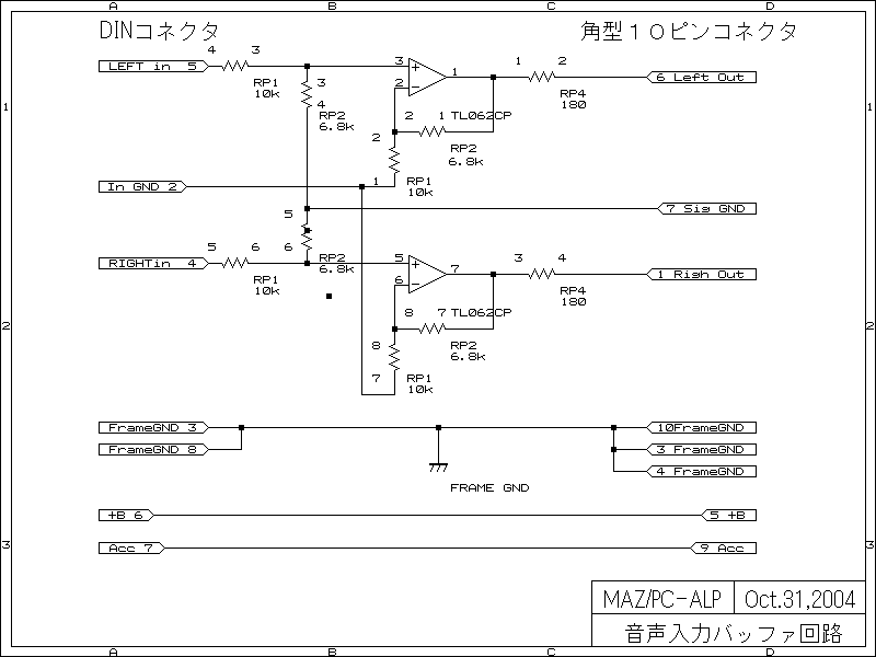
DIN connector is on the left and white square connector is
on the right.
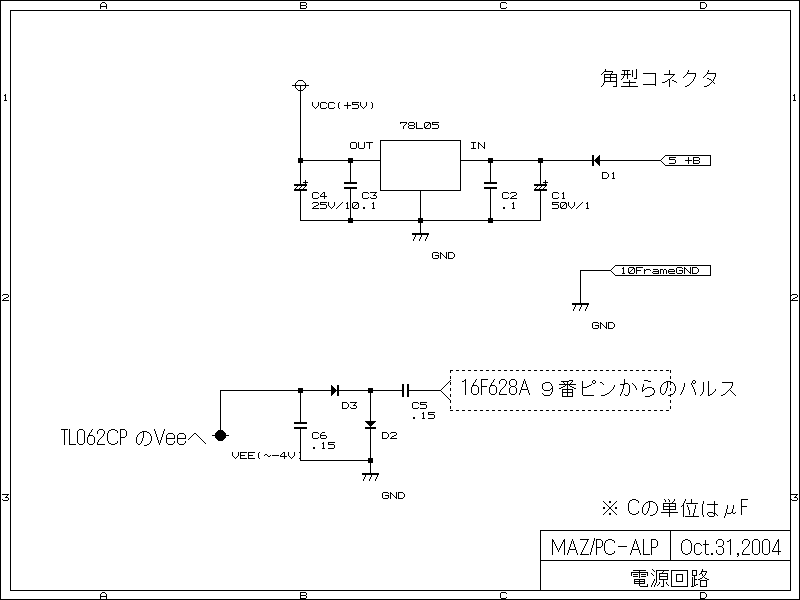
Vcc(+5V) is generated from +B by voltage regulator IC.
Vee(-4V approx.) is generated by pump up the pulse from PIC, this is not
regulated.
| Signal | Pin# | Functions |
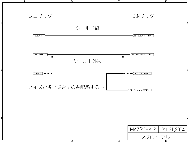
| LEFT in | 5 | Left audio signal from AUX device |
| RIGHT in | 4 | Right audio signal from AUX device |
| In GND | 2 | Signal Ground for Input |
DIN connector is on the left and white square connector is on the right.
Pin1 of 16F628A(PIC) receives the control signal from HU and Pin2 sends the signal to HU. Both signal use the same signal line Bus+.
This diagram may contain some error since I checked only
the parts required for the purpose.
+B from HU is regulated to Vcc(+5V) by regulator IC.
Pulse signal from PIC is charge pumped to make Vee(-4V approx.) which is not
regulated.
There are five register arrays as follows.
DIN input cable can be made if you are familiar with soldering iron.
The connector to AUX devices depend on the device you are going to use. The most popular connectors are 1.Mini-Plug (iPod) and 2.RCA jack (DVD Player.)
Please note that the environment in the car is extremely harsh to those delicate connectors. Chose high quality parts to avoid un-stable contact problems.